Thursday 20 October 2016

20.10.16 Mail box sensor

I had an idea to use a cheap wireless doorbell to let me know when post has arrived to avoid continually checking especially when I am expecting an important parcel.

Chose a 'Lloytron' wireless door chime with a plug in sounder on ebay - works well, all but two of the 'tunes' are so cheesy and awful they are embarrassing to play.  So toss up between an electronic version of a knock at the door and ding-dong!

Bought the equivalent of a mercury switch from Maplins, seems to contain a ball bearing which makes the contact.

Dismantled the bell push and soldered the tilt switch across the contacts, adjusted the tilt, reassembled and used some double sided foam to attach the bell push to the underside of the mail chute.

Seems to work perfectly, now waiting for the next pizza flyer to test it!!


Sunday 16 October 2016

Windows, doors and gates

I have neglected the blog for 12 months so have a few items to catch up.
Most recent tasks have been fiddly, time consuming and on completion hardly seem worthy of a mention, but here are a few with some technical details:


Rear door threshold
The main contractor did not provide a threshold to the main rear doors and the solution was necessarily going to involve some careful detailed design and construction.  At the tail end of the project with pressure on to complete it seemed safer to take this on-board myself.

The rear doors should have included a timber threshold as part of the door frame but we were presented with a wide, insulation filled cavity wall.

The silver lining was that a timber threshold would have been unsophisticated and presented an obstacle to wheeled traffic, so there was an opportunity to come up with something better.


Initially I designed a single pressed stainless steel section incorporating a stepped threshold at the rear of the doors and sloping sections at each edge to to suit ground levels.  The metalworkers could not press this section and suggested it was made in 2 parts.

I thought it might be possible to bolt the sections together but in practice it was impossible to retain the nuts on the rear of one section and fix 'blind' with any certainty.

Although the  metalworkers were dubious, what did work was tapping a hole in the outer section of threshold and bolting through the lap with mushroom headed set screws.

Assembly was tricky in aligning the sections and injecting expanding foam between timber wedges in the correct quantities.  Too little was injected at the inner threshold, so some deflection movement was evident and too much under the external threshold forced it up, despite lots of heavy ballast.

The timber frame was cut back internally to allow the threshold to be installed and glued back in place on completion.

Some really effective drop seals were added to the base of the door and self adhesive dense foam added to lock cut-outs and overlaps to improve airtightness.

The original design allows for the doors (with solid cores) to be enhanced by addition of an insulated liner at a later date.  I cannot see this being a priority since the airtightness is good and the lobby is unheated.  There is an opportunity to add draught seals and drop seals to inner lobby doors that might be more beneficial.

Weather stripping was removed for painting to give a neat finish using Dulux Weathershield - a bit shiny but good colour to match windows etc.


Window
Early one morning in the spring,  unfortunately, I was not woken by an unwelcome visitor when the workshop was broken into. The side window next to the pavement was smashed through using a brick.  I was under the illusion that a toughened outer pane and laminated inner pane and window lock would offer some resistance!

Very thankfully I was insured for break-in damage and the window manufacturer, Rationel, efficiently and quickly organised a replacement unit from Poland and a few accessories; new locking handle, mastic and home-made glazing paddle.  I fitted the unit myself which helped to cover the cost of my insurance excess and I learnt how straightforward the glazing system is in the process!
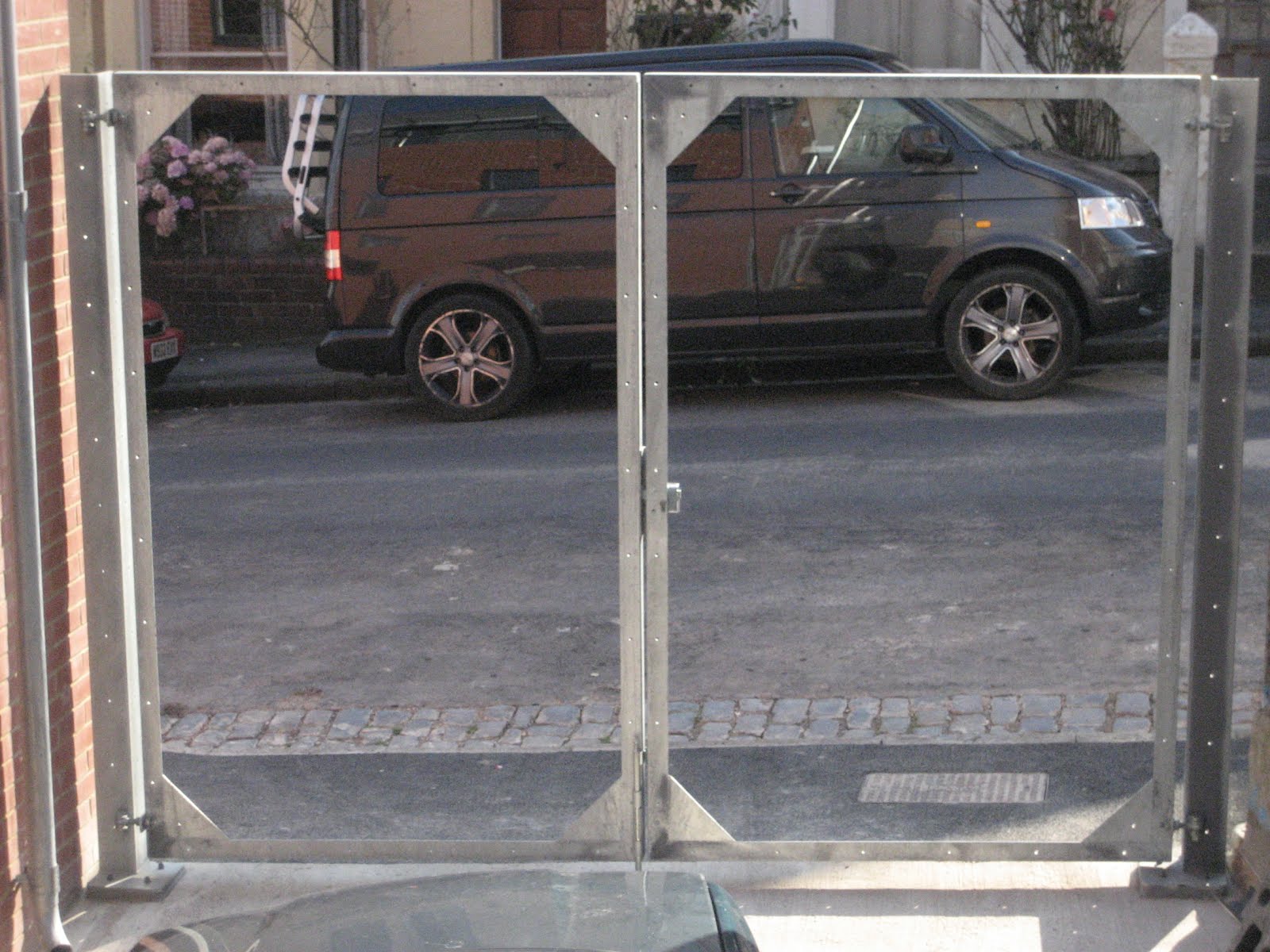

Gates
The break-in spurred me to complete the gate infills using hit and miss arrangement of cedar boards.  The design was based on galvanised angle frames with lots of holes to accept fixings without further drilling and a sandwich arrangement of timbers made up in panels to avoid external fixings.
I was a bit disappointed by the quality of the timber because it was rough sawn timber shoved through a planer so in many cases damaged faces from forklifts or undersized boards etc.  were impossible to conceal since all faces of timber were visible.


The result is great;
  • the wind blows through the gates without deflecting them 
  • the extreme lightness (although cedar is technically a hardwood, think: balsawood) did not add deflection to the gate frames
  • the locking is concealed and works well.
  • the slatted arrangement allows the yard to remain private but gives an awareness of movement in the street and  during the day allows an oblique view from the workshop to the street


Rainscreen
Finally the lower section of the rainscreen is complete after the upper section was finished 12 months ago.
This was the most fiddly part, although accessible from ground level without scaffolding there was a lot to coordinate and plenty of existing construction to rectify.

Mailbox - I wanted a parcel box of some description to accept parcel deliveries and plenty of mail while I was away, but it had to be energy efficient; insulated and draught-proof.   After much detailed design work I concluded that for the effort involved a simpler solution was to accept a proprietary mail box accessible only from the outside.  I found a suitable model in a modern design and in a dark grey which almost matched doors and windows, just a few RAL numbers out.  I cut out a hole in the existing insulated cladding, upgraded the insulation using 2 layers of 50mm Xtratherm and made a 'shoe-box' in birch plywood to accept the mail box.  The box was lined with an uncut sheet of Tyvek Facade 'origami' style. 


Gas Meter enclosure - I have painted the white plastic? box using a recommended Dulux system in grey RAL.  Looks just about OK but the crude design means that the door removes paint at the hinges and the paint finish will always be vulnerable to scratches.  I did originally look at concealing the whole box behind the cedar rainscreen, but this was a coordination step too far and would have required an enormous depth of wall.
 
Door Intercom - This had been mounted on a huge piece of timber spanning between vertical battens that completely blocked the ventilation space necessary behind the Tyvek Facade.  I replaced this timber with 15mm birch plywood on small battens and added a shaped packer in Iroko to bring the Intercom out to the finished face of rainscreen.  As it happens my calculations were wrong so later the intercom had to be lowered once detailed calculations of slat positions were made.  This was especially painful given the spaghetti of telephone wires in the unit that required dismantling and reconnecting.

Tyvek Facade - Is a water resistant but breathable membrane in matt black finish without the normal 'Du-Pont Tyvek' writing.  It requires a ventilation space between it and the insulation behind to allow moist air to escape and avoid condensation or a 'steaming' effect.  Tyvek facade is not totally UV stable and since the original installation had been made without the ventilation gap I was aware that this would require replacement.  In fact the Tyvek had started to loose its flexibility and was in any case dirty and not quite so matt and pristine.  The contractor had left me with the remainder of a 50M roll of Tyvek which turned out to be only just enough, and I really did not want to buy another roll at £220 for a couple of metres!  Tyvek has deleted the double sided tape that I needed to join new and remaining membrane so a 3M substitute from  RS Components had to do.

Alignment - the existing battens that secured insulation to timber studs were neither vertical nor offered a flat surface for the rainscreen.  So after the Tyvek membrane was removed birch plywood packers in 1mm increments were added to give a flat and true surface.
Door Jambs - The door & window/cladding contractor installed powder coated door jamb flashings but secured them with small aluminium angles using mastic, without first removing the protective plastic:(  So the jambs were glued to protective plastic!  Given the lack of attention and poor workmanship I negotiated with the cladding contractor to supply me with 2 full height pressed aluminium angles and we would call it a day.  Unfortunately the contractor shut the pair of angles in his car door before driving from Dudley and spent time trying to hammer out the banana shapes on site.
I debated if I could use these slightly bent sections, removed the old angles and used some fantastic 3M double sided 1mm foam adhesive to join angles to rear of jamb flashings.  The angles were first drilled with slotted holes to allow them to be fixed flat and slid into contact with jamb flashings and the release tape made accessible so it could removed at the last minute.  
The aluminimum angles were also sprayed matt black where they remained visible.
Wall junction - A continuous strip of Compriband sized to expand and seal the variation in brick and mortar joints was applied to the brick wall. A pressed light gauge angle of galvanised steel  fixed to perimeter battens, sealed the Tyvek membrane against the Compriband.  It was found that the matt spray paint would not stick to the galvanized angle so a strip of Tyvek was reversed and joined with double sided tape to give a matt black finish where this was visible at the perimeters.
Templates - Once the Tyvek was complete, thin plywood templates were made for left and right sections and the precise spacing of cedar planking calculated.  Gaps between planks are progressively adjusted to allow for gap spacing around each obstruction and achieve the desired head condition, although gaps appear equal.

Wednesday 21 October 2015

21 Oct 2015 Cedar Louvres / Kitchen


Western Red Cedar rainscreen cladding

Master craftsman Steve fixing centre panel with template in place below
On return from holiday in France the perfectly timed weather was dry and sunny for a whole week, allowing me to strip off the all protective black Tyvek, applied without ventilation top and bottom (and becoming brittle in the sun).
The battens were checked for plumb and flatness and packed up to 18mm using birch plywood continuous packers in 1mm increments. New Tyvek 'Facade' with matt black outer face was stapled into place with double sided tape lap joints and 40mm air gaps for ventilation to the cavity. This membrane is weatherproof but vapour permeable allowing the cavity and wall to breath.  

Vertical 15x50mm light gauge galvanised steel angles were screw fixed to the perimeter battens with a Compriband sealing strip between the edge of the Tyvek and brickwork.
Compiband though expensive can be installed in a very precise manner and will slowly expand after installation to form a weather proof seal.  The edge of the Tyvek was 'hemmed' using a narrow double sided tape to conceal the white cut edge and give a sharp black line.  The exposed face of the galvanised angle and the aluminium  input and extract grilles were painted matt black using bitumen emulsion weatherseal.

Fortunately the Lindab downpipe was able to be swung out of the way to allow access for installation and fixing of louvre panels without totally dismantling.

The Youngman Boss scaffolding tower is well designed,  easy to erect and dismantle by one person and pretty stable when full height; highly recommended!


The upper 3 sections of cedar cladding were prefabricated in the workshop in accordance with full sized templates all using the same lozenge profile cedar sections. The top and bottom louvres fixed flat onto battens and the middle section edge-on.  All louvres generally fixed using concealed decking screw fixed from the rear.  The edge-on louvres allow sufficient gaps to allow airflow to and from the ventilation system and also allow a view out of the first floor window and giving visual interest from the street at dusk.

The lower section of louvres will now be completed, though not requiring scaffolding they are more fiddly, incorporating door intercom, gas meter box and and internal insulated letter box yet to be detailed!


Kitchen 

The kitchen  has been complete for some time with shelves and tiling as the final details, (kickspace upstand still outstanding!).  The floor tiles worked well as wall tiles though a black grout was used to mimic the gaps between cabinet doors and drawers.  Careful and time consuming cutting of tiles was necessary because they are monolithic fired material as opposed to glazed tiles.


Friday 28 August 2015

27 August 2015 - Photo Voltaic Installation

Local News
Healthy scepticism?
The state of over-gentrification can be judged by the number of sample pots?

PV Installation
 
In May 2015 I naively clicked a banner ad on my laptop promising comparative prices for PV installation, I was curious because it was always 'in the plan' but just not a high priority.  What I realised the following day was that this was just a sales-lead gathering website for contractors and some of whom also install double glazing, roofing, cavity wall insulation etc.......

Since only a handful of contractors phoned me, I made appointments with 3 or 4 for no obligation quotes.  It became apparent that most PV contractors are used to quoting for pitched roofs, where apart from the kit there are 2 fixed variables; roof pitch and orientation, so the 'surveyor' has only to work out how many panels can be fitted.  My roof is flat and fairly limited in size, with the pitch and orientation of panels almost infinitely variable - a clean sheet so to speak.

One contractor offered a totally flat layout, which would have necessitated regular cleaning, another proposed a south facing pitched arrangement but by my calculation the arrays were larger than the available roof space.  All contractors majored on Warranties,  which I found off putting because I wanted a company I felt I could trust, without relying on guarantees that should only be a last resort.

Since I was now fully up to speed on Photo Voltaics from initially very little knowledge, it seemed logical to continue through to an installation.  I did a bit of research mainly through trusted Electricians and came up with 3 likely PV Installers.

I had an intelligent 2-way conversation with the surveyor from Solarsense, rather than a sales pitch, who understood that I was after value for money that could be expressed in the payback period and was able to consider all the variables in a flat roof installation. 
Solarsense were also experienced and confident in specifying flat roof installations that relied on ballasted frameworks.

A couple of layouts were explored in outline and the favoured one analysed in more detail.  The installed layout dispensed with the desire to face due south at an angle across the roof and instead lined 2 rows of panels, pitched back to back and square to the roof layout.  This gave a dense layout and the low pitch of 10º (to aid self cleaning) and meant that the panel surfaces would receive light for a wide part of the day with only a small reduction in efficiency due to the low pitch.   This arrangement also had the advantage of a fairly streamlined profile, so ballast to prevent uplift and movement could be kept to a minimum, though still weighing a tonne!
In an effort to reduce installation costs I suggested that the house stairs and rooflight could be used to transfer materials to the roof, as an alternative to external scaffolding, in addition I offered to move ballast to the roof. 

After some rather lengthy discussions with the framework manufacturer in Germany and checks by the Engineer the ballast layout was agreed. 
The most convenient and economic form of ballast I could find was concrete path edging,  61 were required each weighing 16kg.  These were cut as necessary at ground level, carried to 2nd floor and then by an ingenious sledge contraption dragged onto the roof;  thanks to Miles, Gillian & Webster for lending a hand!

Safety scaffolding was erected and the installation took a little over a day, the layout fits the roof area neatly with walkways to get to all roof areas.


I am especially pleased with the electrical installation, where switches, a meter and the large inverter all fit snugly into the available space next to existing electrical equipment.


Today is the first day of generating electricity, monitored via WiFi and smartphone app.  
In a couple of days I will have the necessary paperwork to allow my electricity supplier to pay me every 3 months depending on electricity generated...... after I have paid for the installation. 

Wednesday 19 August 2015

Kitchen & Solar Panels


Kitchen awaiting tiled finish and sockets.
Pleased with grey Hexboard finish, although the reverse face was not smooth grey as promised but a standard dark brown phenol.  Thankfully and by a stroke of luck the cabinets are black and not the normal white so the finished combination looks 'OK'!
The front panel on the dishwasher was pretty tricky and almost impossible to finely adjust.
Lighting is a bit disappointing, I decided that the space above the wall units was a bit dark so wanted a linear light, so experimented with LED tape.  Very neat components but the colour match is very poor with a green tinge although the colour temperature is the same.  May take this up with the LED supplier when I have a moment but can't see me getting far.
I need to come up with a neat solution to disguise the extract grille


The bracing to solar panels was installed some time ago.
The neatest solution would have been to rely on ballast to prevent uplift and horizontal movement but the loads proved too high for the roof structure.  The only practical solution was to use ballast to resist uplift and restrain the frames from horizontal movement.  Rather than bespoke metalwork off the shelf scaffold type components were utilised.  Fixings were only practical at parapet height for weathering reasons and the top of the timber framed construction offered practical fixing locations.
Purpose made U-bolts connect the frames to tube structure
.


Thursday 30 April 2015

MVHR - Remedial Work

MVHR
The MVHR (Mechanical Ventilation & Heat Recovery) seems to be working well and silently. The automatic programme works continuously and is currently set with fan speed 2 at night and 1 during the day, these can be altered to suit occupation   A temporary 'boost' fan speed 3, can be switched on when cooking or after the shower is used to purge spaces of smells or excessive humidity and operates for a set period - currently 45mins, via a bell-push switch in the kitchen.

Spot the typo

Filters
The frequency of filter changes (recommended between 3 - 12 months) depends on several factors;  intensity of use of ventilation system and amount of internal and external contaminants.  The purpose of filtering is to remove airbourne contaminants from entering the dwelling; fumes, dust, pollen etc. and most importantly to protect the very low power fans from clogging up.  

I read that an MVHR user had installed a power meter to measure watts used by fans to help determine when to change filters that are quite expensive (3 filters @about £12 each).

I installed a meter measuring power in watts, but  the increased consumption hardly registers.  The fans are constant volume so as the filters become blocked the fans work a little harder to move the same volume of air.  We are now approaching 1 year of occupation so I have changed filters.  The main filter that protects the frost heater was pretty dirty, fairly black from city pollutants.


Insulation
It is very important to insulate the incoming and outgoing ducts to avoid condensation which would form if warm humid air inside came into contact with steel ducts that could be approaching freezing temperatures.  

The MVHR system is provided with a heater battery (contained in the dark grey square polystyrene box), to warm air during very cold periods and a condensation drain in the MVHR fan unit.

The original insulation installed around the incoming ducts was an incorrect specification, (foil covered mineral wool) and the insulation was not in contact with the external wall insulation. For some reason the correct Armaflex insulation went missing towards the end of the contract, so I elected to install the replacement materials myself.


I stripped off the MDF patris around outgoing ducts  and found that the holes through outer walls were a bit hit and miss and were not sealed airtight, or fully insulated.


Externally some 'making good' was required around ducts and fortunately I was able to get a sufficient offcut of the insulation board.  The voids were neatened up, and tight-fit infill pieces cut on the bandsaw and finished with expanding foam.   The external aluminium grilles were relying on friction fit so I made some birch ply panels and drilled the grilles to secure them.


Insulation repaired
External duct inlet


Cutting insulation from template on bandsaw


Internally I made some thin birch ply surrounds, close fitting around ducts to give support and close the gaps around OSB.


Plasterboard damage was repaired, missing Rockwool insulation replaced and enlarged holes cut by hand around duct and silencer. These holes were cut 60mm larger than ducts to allow the total thickness of 50mm Armaflex to be in close contact with the wall structure.
Walls were filled and plasterboard re-painted. 


Ductwork was reassembled, with addition of a small shelf to support the frost heater.   Armaflex, a lightweight and flexible insulating foam with a skinned surface, was added in two 25mm thicknesses.


Cutting schedule
Armaflex is fairly easy to work with with a sharp kitchen knife and careful measurement, although the surface is pretty fragile and snags quite easily with finger nails for example.  

I did spend some time plotting out how each section was to be cut to ensure I had enough material and reduce wastage. 


Printed pattern transferred to cardboard template


The corners are made by using 90º or 45º templates transferred onto cardboard and gluing 2 sections together to make pre-formed corners.  
All butt joints are made using a very runny contact adhesive with a consistency of golden syrup and the finished joints neatened and reinforced with self adhesive foam tape.


A few missing ductwork seals were installed


Preformed corners made from 2 pieces of Armaflex with curved butted joints


Finished job